Wireguard Client
Listing:
apt-get install openresolv
ip link add wg type wireguard
wg show
nano /etc/wireguard/wg.conf
wg-quick up wg
ip address
ping 10.8.0.2
wg show
- Service:
- systemctl enable wg-quick@wg
- systemctl daemon-reload
- systemctl start wg-quick@wg
=>systemctl list-units|grep wg
Routing:
apt-get install iptables
iptables -A FORWARD -i wg0-client -j ACCEPT
iptables -t nat -A POSTROUTING -o enp1s0 -j MASQUERADE
sysctl net.ipv4.ip_forward=1Wireguard Tunnel all Internet traffic but have access to local printer
This AllowedIps: 0.0.0.0/0 setting routes all traffic thru Wireguard even LAN, which makes printing impossible.
How can I exclude printing from this, so I can print using my local wireless printer but still route all Internet traffic thru Wireguard VPN?
Windows client
Wireguard server is on VPS
2 Answers
On your Windows machine, edit the tunnel in the WireGuard client, and un-check the Block untunneled traffic (kill-switch) checkbox (at the bottom of the Edit tunnel dialog box). When checked, this setting effectively prevents Windows from using the other routes in its routing table.
If that alone doesn't fix it, you may also need to add a static route specifically for your printer. Try running route print in a command prompt on your Windows machine -- this will display your existing route table. If a route to your printer (or to the subnet your printer is on) is not listed, try adding one manually by running route add <printer ip address> <router ip address> in the command prompt -- for example, run route add 192.168.1.2 192.168.1.1 if 192.168.1.2 is your printer's address, and 192.168.1.1 is your local router's ip address.
If adding a static route fixes it, you can add the route permanently (ie persisting after restarts etc) by adding the -p flag (eg route -p add 192.168.1.2 192.168.1.2); or later delete the route by running route delete <printer ip address> (eg route delete 192.168.1.2).
In my experimentation, I'd recommend keeping AllowedIPs intact as 0.0.0.0/0. Instead, take advantage of the PostUp and PreDown steps in your wireguard config.
If you're downloading your killswitch configs from Mullvad, these steps are already included. All you need to do is add your local network to the iptables exclusion.
So the following config from Mullvad:
[Interface]
PrivateKey = ###################################
Address = ##.##.##.##/32,####:####:####:####::3:5d1f/128
DNS = ##.##.##.##
PostUp = iptables -I OUTPUT ! -o %i -m mark ! --mark $(wg show %i fwmark) -m addrtype ! --dst-type LOCAL -j REJECT && ip6tables -I OUTPUT ! -o %i -m mark ! --mark $(wg show %i fwmark) -m addrtype ! --dst-type LOCAL -j REJECT
PreDown = iptables -D OUTPUT ! -o %i -m mark ! --mark $(wg show %i fwmark) -m addrtype ! --dst-type LOCAL -j REJECT && ip6tables -D OUTPUT ! -o %i -m mark ! --mark $(wg show %i fwmark) -m addrtype ! --dst-type LOCAL -j REJECT

[Peer]
PublicKey = ###############################
AllowedIPs = 0.0.0.0/0,::0/0
Endpoint = ##.##.##.##:####
Turns into the following, where I've excluded my local network 10.0.0.1/24, and to improve readability, split the concatenated PostUp and PreDown steps into two steps each:
[Interface]
PrivateKey = ###################################
Address = ##.##.##.##/32,####:####:####:####::3:5d1f/128
DNS = ##.##.##.##
PostUp = iptables -I OUTPUT ! -o %i -m mark ! --mark $(wg show %i fwmark) -m addrtype ! --dst-type LOCAL ! -d 10.0.0.1/24 -j REJECT
PostUp = ip6tables -I OUTPUT ! -o %i -m mark ! --mark $(wg show %i fwmark) -m addrtype ! --dst-type LOCAL -j REJECT
PreDown = iptables -D OUTPUT ! -o %i -m mark ! --mark $(wg show %i fwmark) -m addrtype ! --dst-type LOCAL ! -d 10.0.0.1/24 -j REJECT
PreDown = ip6tables -D OUTPUT ! -o %i -m mark ! --mark $(wg show %i fwmark) -m addrtype ! --dst-type LOCAL -j REJECT

[Peer]
PublicKey = ###############################
AllowedIPs = 0.0.0.0/0,::0/0
Endpoint = ##.##.##.##:####
You can exclude additional ipv4 IPs by adding additional ! -d ##.##.##.##/## before the line's -j REJECT. The same can be done for ipv6 in the ip6tables commands.
Here's a quick python script I threw together to update all of my configs with my ipv4 exclusion. It'll preserve existing exclusions, split concatenated PostUp and PreDown commands, and save the original to .old. Sample usage: python3 excludeIpv4.py 10.0.0.1/24:
# excludeIpv4.py
import os
import sys

path = "/path/to/your/configs" # << change this
configFileEnding = '.conf'

os.chdir(path)

excludeIpv4 = sys.argv[1]

# will add ip exclusion to PostUp and PreDown steps
# will split concatenated PostUp and PreDown steps
# will preserve existing IP exclusions
def modifyFile(filePath):
    dnsIdx = -1
    newFileContents = []
    existingExclusion = "! --dst-type LOCAL"
    newExclusion = f"! --dst-type LOCAL ! -d {excludeIpv4}"
    renamedFileName = filePath + ".old"

    with open(filePath, 'r') as f:
        fileContents = f.read().split("\n")
        for line in fileContents:
            if line.startswith("#"):
                continue

            # modify PostUp
            if line.startswith("PostUp"):
                newLines = line.split(" && ")
                for newLine in newLines:
                    if not newLine.startswith("PostUp"):
                        newLine = "PostUp = " + newLine
                    if newLine.find("iptables") > -1:
                        newLine = newLine.replace(existingExclusion, newExclusion)
                    newFileContents.append(newLine)

            # modify PreDown
            elif line.startswith("PreDown"):
                newLines = line.split(" && ")
                for newLine in newLines:
                    if not newLine.startswith("PreDown"):
                        newLine = "PreDown = " + newLine
                    if newLine.find("iptables") > -1:
                        newLine = newLine.replace(existingExclusion, newExclusion)
                    newFileContents.append(newLine)

            else:
                newFileContents.append(line)

        # save original file to new file
        with open(renamedFileName, 'w') as f:
            f.write("\n".join(fileContents))


    # write new content to new file
    with open(filePath, 'w') as f:
        f.write("\n".join(newFileContents))

    return renamedFileName, filePath


print(f"Adding IPv4 exclusion of '{excludeIpv4}' to '{configFileEnding}' files in '{path}'...\n")
for file in os.listdir():
    if file.endswith(configFileEnding):
        filePath = os.path.join(path, file)
        print(f"Modifying {filePath}...")
        renamed, new = modifyFile(filePath)
        print(f"File updated. Saved original to {renamed}\n")
-----------------------------------------------------------------------------------------------------------------------------------
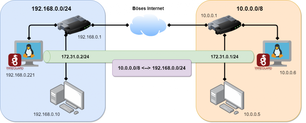
WireGuard Site to Site VPN – Zwei Netzwerke sicher verbinden
WireGuard ist der “neue” VPN Server von Heute! Nicht das er als Open Source sowieso schon bei mir gewonnen hat, sondern er ist auch ein Leichtgewicht. Der schlanke SourceCode bringt ihm zusätzlich Performance, sodass wir alles an Board haben was wir brauchen.
Zusammengefasst, WireGuard ist ein sehr einfacher, sehr sicherer und sehr schneller VPN Server für alle möglichen Plattformen und Betriebssystemen.
Im letzten Video habe ich euch gezeigt wie man eine Client to Site Verbindung herstellt und habe euch die Konfiguration dazu hier im Blog aufgeschlüsselt. (WireGuard Client VPN)
Jetzt zeige ich euch wie man eine Site-to-Site VPN Verbindung herstellt und dann die Netzwerke auf der gegenüberliegenden Seite erreicht.
Anleitung: WireGuard Site-to-Site VPN Server
Schritt 1: Auf dem SERVER1 und SERVER2 ausführen
|
1
2
3
4
|
sh -c "echo 'deb http://deb.debian.org/debian buster-backports main contrib non-free' > /etc/apt/sources.list.d/buster-backports.list"apt updateapt install linux-headers-$(uname --kernel-release)apt install wireguard |
|
1
2
3
|
nano /etc/sysctl.conf# <- entfernen bei der Zeile "net.ipv4.ip_forward=1" und speichernsysctl -p |
|
1
2
3
4
5
|
cd /etc/wireguard/umask 077; wg genkey | tee privatekey | wg pubkey > publickeycat privatekeycat publickeychmod 600 /etc/wireguard/privatekey |
Schritt 2: Nur auf SERVER1 ausführen
Konfigurationsdatei anlegen
nano /etc/wireguard/wg0.conf
[Interface]
PrivateKey = <Dein privater Schlüssel [privatekey SERVER 1]>
Address = 172.31.0.1/24
SaveConfig = true
PostUp = iptables -A FORWARD -i wg0 -j ACCEPT; iptables -t nat -A POSTROUTING -o eth0 -j MASQUERADE
PostDown = iptables -D FORWARD -i wg0 -j ACCEPT; iptables -t nat -D POSTROUTING -o eth0 -j MASQUERADE
ListenPort = 51820

[Peer]
 PublicKey = <Öffentlicher Schlüssel von [SERVER 2]>
 AllowedIPs = 192.168.0.0/24, 172.31.0.0/24
 PersistentKeepalive = 25
In den Zeilen PostUP & PostDown das Interface anpassen wie es zu eurem System passt. Hier steht jetzt eth0, das kann aber bei euch anders sein. Prüfen könnt Ihr das mit “ip a“
Schritt 3: Nur auf SERVER2 ausführen
Konfigurationsdatei anlegen
nano /etc/wireguard/wg0.conf
[Interface]
PrivateKey = <Dein privater Schlüssel [privatekey SERVER 2]>
Address = 172.31.0.2/24
SaveConfig = true
PostUp = iptables -A FORWARD -i wg0 -j ACCEPT; iptables -t nat -A POSTROUTING -o eth0 -j MASQUERADE
PostDown = iptables -D FORWARD -i wg0 -j ACCEPT; iptables -t nat -D POSTROUTING -o eth0 -j MASQUERADE

[Peer]
PublicKey = <Öffentlicher Schlüssel von [SERVER 1]>
Endpoint = <ServerIP oder Domain/FQDN>:51820
AllowedIPs = 10.0.0.0/8, 172.31.0.0/24
PersistentKeepalive = 25
Schritt 4: Auf SERVER1 und SERVER2 ausführen
|
1
2
3
|
wg-quick up wg0wg##Das zeigt dir den Status der Verbindung an |
Das wg-quick Kommando startet die Wireguard Verbindung mit der entsprechend hinterlegten Konfiguration, welche wir im vorherigen Schritt erstellt haben. Wenn eure Konfigurationsdatei anders heißen sollte, müsst Ihr den Befehl natürlich anpassen. wg0 ist hier nur als Beispiel genommen.
Schritt 5: Autostart (Server1 & Server2)
Wenn WireGuard automatisch mit dem System starten soll, dann folgenden Befehl absetzen.
|
1
|
systemctl enable wg-quick@wg0 |
Schritt 6: Routing
Ihr müsst natürlich auf beiden Seiten für das Routing sorgen. Hier ein Auszug aus dem Video wie das Routing in der Fritzbox aussehen könnte.
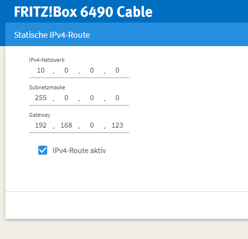
Wireguard Netzwerk mit Routing einrichten
Wireguard Netzwerk
Die prinzipielle Einrichtung von Wireguard habe ich in dem Artikel Wireguard beschrieben. Es ging um die die Point to Point Einrichtung mehrerer Clients die auf einen PC, der als Server fungiert, zugreifen. Die Clients konnten sich untereinander nicht sehen.
Im folgenden möchte ich beschreiben, wie man ein VPN Netz aufbaut in dem sich die Clients untereinander verbinden können. Damit Clients in dem privaten Netzwerk sich über Hostname ansprechen können, wird ein zentraler DNS Server eingerichtet. Hierfür verwende ich einen vorhandenen OpenWRT Router.
Aufbau des Netzwerkes
Das Netzwerk ist auf mehrere Standorte verteilt. Es gibt einen zentralen Linux PC der die Rolle des Wireguard Servers einnimmt. Die Rolle einnimmt, weil es per se keinen Wireguard Server gibt. Es ist die Konfiguration die ihn zur Zentrale werden lässt. Damit dieser erreichbar ist, ist ein DynDNS Dienst oder eine feste IP Adresse von Nöten. Dieses ist aber nicht Bestandteil dieses Artikels. Hier verwaise ich zum Beipsiel auf den Artikel DynDNS mit Duck DNS.
Der Server bekommt in dem VPN die Adresse 10.0.0.1. Der Server ist für das Routing unter den Clients verantwortlich. Das heißt er leitet eingehende Pakete an die anderen Clients weiter. Hierfür muss das IP Forwarding aktiviert und einfache Regeln für die FORWARD Chain von IPTABLES angelegt werden.
Die Clients stellen eine Reihe von Laptops, Workstations und weiteren Servern da. Die Client erhalten durchnummerierte IP Adressen beginnend mit 10.0.0.2/32. In meinem Setup sind es aktuell 6 weitere PCs die in dem VPN vorhanden sind.
Konfiguration von Wireguard
Im Folgenden werde ich das Schema wie Clients und der Server einzurichten sind erläutern. Wenn das Schema bekannt ist, dann ist es leicht weitere Clients hinzuzufügen.
Einrichtung auf dem Server
Das Schema ist eigentlich recht einfach. Es muss allerdings auf die Subnetzmaske bei der Angabe der IP Adressen genau geachtet werden. Die Server Adresse ist mit /24 und die Clients mit /32 anzugeben.
[Interface]
PrivateKey = PrivateKeyDesServers
ListenPort = 32768
Address = 10.0.0.1/24

# Allow routing between clients
PostUp = iptables -A FORWARD -i %i -j ACCEPT; iptables -A FORWARD -o %i -j ACCEPT
PostDown = iptables -D FORWARD -i %i -j ACCEPT; iptables -D FORWARD -o %i -j ACCEPT

#
# Client 1
#
[Peer]
PublicKey = PublicKeyDesClient
AllowedIPs = 10.0.0.2/32

#
# Client 2
#
[Peer]
PublicKey = PublicKeyDesClient
AllowedIPs = 10.0.0.3/32

#
# Client 3
#
[Peer]
PublicKey = PublicKeyDesClient
AllowedIPs = 10.0.0.4/32

.
.
.

#
# Client 7
#
[Peer]
PublicKey = PublicKeyDesClient
AllowedIPs = 10.0.0.7/32
Einrichtung der Clients
Es ist hierbei wichtig zu wissen, dass nur ein Client das gesamte Subnetz beanspruchen darf! Sonst funktioniert das ganze nicht. Das heißt auf den Clients sind explizit die Adresse einzutragen mit denen der Client kommunizieren darf. Dieses macht aber nur bei kleineren Netzen einen Sinn.
[Interface]
PrivateKey = PrivateKeyDesClients
Address = 10.0.0.3/24
DNS = 10.0.0.7

[Peer]
PublicKey = PublicKeyDesServers
AllowedIPs = 10.0.0.1/32, 10.0.0.2/32, 10.0.0.5/32, 10.0.0.6/32, 10.0.0.7/32
EndPoint = myname.dyndns.org:32222
PersistentKeepalive = 25
Wichtig ist das alle Clients mit 10.0.0.X/32 angegeben werden.
IP Forwarding Aktivierung
Das allgemeine IP Forwarding bzw. auf Geräteebene aktivieren habe ich bereits in dem Wireguard Artikel beschreiben.
Firewall Regeln
Damit die Pakete nun auch an die Client weitergeleitet werden, muss in der FORWARD Chain das In-/Output auf dem Wireguard Interface zulassen. Dieses kann mit dem PostUp in der Konfiguration automatisch nach dem Starten der Verbindung durchgeführt werden.
PostUp = iptables -A FORWARD -i %i -j ACCEPT; iptables -A FORWARD -o %i -j ACCEPT
Verbindungsaufbau
Für den automatischen Verbindungsaufbau muss die Option PersistentKeepalive gesetzt werden, damit ein Paket Verbindung öffnet.
Einrichtung von DNS
Auf dem Client habe ich die Konfiguration mit dem KDE NetworkManager durchgeführt. Bei der Wireguard Konfiguration habe ich nun die Adresse des DNS Servers eingetragen, der für das interne Netzt zuständig ist. Die Konfiguration der statische Hostnames beschriebt ein andere Artikel.
Testen der Namesauflösung
Auf http://openwrt/cgi-bin/luci/admin/network/dhcp unter Local Server mit /XXXX.duckdns.org/ Anfrage an die Domain nach außen unterbinden, da diese sonst von DuckDNS beantwortet werden würden und somit die IPV6 Adresse genommen wird, was zu Fehlern führt.
Block untunneled traffic (kill-switch)only appears if your (on client machine) peerAllowedIPs = 0.0.0.0/0